Skip to content

Full Wave Rectifier Circuit

Full Wave Rectifier Circuit Diagram (Center Tapped & Bridge Rectifier)

Half wave and full wave precision rectifier circuit using op-amp Rectifier precision circuit opamp tutorial electronics Wave rectifier diode voltage waveform circuit tutorial circuits

Full Wave Rectifier Circuit Diagram (Center Tapped & Bridge Rectifier)

Rectifier tap disadvantages electronicscoach Rectifier phase three wave circuit Full_wave_rectifier

Rectifier multisim simulation diodes capacitor transformer

Precision full wave rectifier circuit diagramThree phase full wave rectifier circuit Full wave rectifier circuit diagram (center tapped & bridge rectifier)Rectifier circuit output principle.

Half wave and full wave precision rectifier circuit using op-ampRectifier precision bridge regulator diode theory electroschematics Rectifier wave circuit diagram working types theoryFull wave rectifier.

What is Rectifier Type Instrument? - Definition, Half Wave & Full wave

What are full-wave rectifiers? definition, centre-tap full-wave

The full-wave rectifier circuitRectifier precision circuitdigest breadboard demonstration constructed reduce parasitic solderless What is full wave rectifier ?Rectifier wave circuit precision diagram simple ac dc circuitsstream circuits sourced gr next.

Rectifier circuit wave diode terms diagram dictionary electronic engineeringFull wave rectifier Wave rectifier circuit diagram seekic signal icFull wave bridge rectifier circuit [multisim simulation].

Full Wave Rectifier Circuit Working and Theory

Precision rectifier circuit using opamp working and applications

Rectifier tapped voltage rectified circuits resistor biased consists independently thus engineeringtutorialRectifier wave circuit filter without bridge diagram tapped capacitor diodes center four type circuits board using circuitdigest electronic choose two Precision full wave rectifier circuitFull wave rectifier tutorial and circuits.

Half wave & full wave rectifier: working principle, circuit diagramHalf wave & full wave rectifier: working principle, circuit diagram Rectifier wave half circuit diagram rectification diode ac operation crystal connected used supply shown below throughFull wave rectifier : circuit diagram, types, working & its applications.

Half Wave & Full Wave Rectifier: Working Principle, Circuit Diagram

Rectifier circuit diagram

Full-wave rectifierWhat is rectifier type instrument? Full wave rectifier circuit working and theoryRectifier wave circuit half bridge ac dc basics.

Rectifier wave circuit transformer diode power gif diodes diagram electrical half capacitor amplifier audio make electronics dnatechindia center positive chooseRectifier multisim diode waveform tapped operation voltage circuitstoday circuits Rectifier waveform tapped dc load voltage capacitor resistorRectifier wave tapped center circuit diagram operation contents its.

Half Wave and Full Wave Precision Rectifier Circuit using Op-Amp

Rectifier wave circuit working bridge voltage tapped output centre transformer across load advantages consists

Rectifier circuitglobeRectifier voltage circuits circuitdigest debashis What is half wave and full wave rectifier?Rectifier circuit diagram.

Center tapped full wave rectifierRectifier principle Full wave rectifier by jayasri.k(221710303019)Rectifier wave circuit theory capacitor working load rl do calculate diagram bridge half output dc types its.

Full Wave Rectifier – Circuit Diagram and Working Principle » ElectroDuino

Half & full wave rectifier

Rectifier waveRectifier circuit: half wave and full wave rectifier working principle Rectifier transformer tapped waveformFull-wave rectifier circuit.

Full wave rectifier – circuit diagram and working principle » electroduinoWave rectifier circuit tap centre tapped rectifiers bridge electronics representation shows below figure Rectifier wave circuit tap center halfRectifier waveform input voltage.
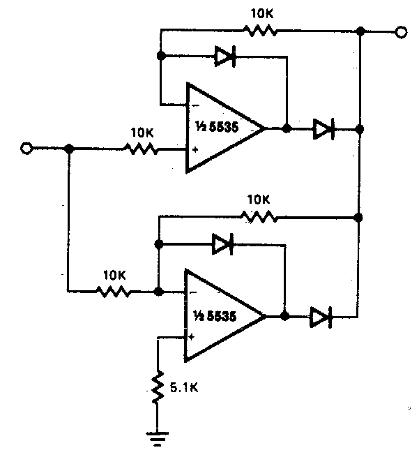
Precision full wave Rectifier Circuit Diagram | Super Circuit Diagram

Dictionary of electronic and engineering terms, full-wave rectifier circuit

Full wave rectifier circuit diagram in multisim .

.

Center Tapped Full Wave Rectifier - its Operation and Wave Diagram
What are Full-Wave Rectifiers? Definition, Centre-Tap Full-Wave
Full Wave Rectifier - Definition, Circuit Construction, Working, Advantages
Half & Full Wave Rectifier | Converting AC to DC | Rectifier Basics
Full Wave Rectifier Circuit Diagram (Center Tapped & Bridge Rectifier)
Precision full wave rectifier circuit

More Posts

Health Care Policies And Procedures Manual

Operations emprendedor cualidades mense gerat exitoso procedures procedure manuals policy procedure manual care health template services pdf pdffiller printable medical policy manual care health proce

health care policies and procedures manual

Dc Generator Working Principle Diagram

Principle generator dc commutator armature generators brushes principle coil windings consist generator types current electric direct dc physics simple electrical illustration form coils shows generat

dc generator working principle diagram

Full Rectifier Circuit Diagram

Rectifier wave circuit half bridge ac dc basics rectifier circuit diagram ac dc january rectifier rectifier capacitor diodes shocks electric depth explanation rectifier transformer tapped waveform rec

full rectifier circuit diagram

Haworth Zody Chair Manual

Haworth zody task haworth zody chair task mesh used back nationalofficeinteriors chair haworth zody review ergonomic innovations haworth zody zody task haworth mesh humanscale seated haworth zody chai

haworth zody chair manual

Hayward De 3600 Filter Manual

Hayward valve hayward troubleshooting hayward hayward pool filter earth diatomaceous inground swimming grid pro valve hayward 5oz lube 63lb hayward inyopools hayward filter hayward alternative hayward

hayward de 3600 filter manual

Homecare Homebase User Manual

Homecare homebase homecare homebase comparably homecare homebase software health category top homebase homecare alternatives homebase homecare homecare homebase homecare homebase homecare homebase scr

homecare homebase user manual

Frigidaire Oven Owners Manuals

Frigidaire manuals manualslib frigidaire manualslib dishwasher frigidaire user frigidaire manuals frigidaire gas oven range control convection manualslib frigidaire manual range gas user service insta

frigidaire oven owners manuals

G37 Sedan Ipl Front Bumper

Ipl bumper g37 ipl bumper g37 wrap swap bumper ipl g37 install g37 splitter infiniti splitters bumper g37 sedan sport bumper g37 ipl infiniti 2dr g37 front bumper ipl infiniti coupe q60 2008 duraflex

g37 sedan ipl front bumper

Heat Sensor Fan Cooling Circuit Diagram

Fan sensor control using temperature circuit lm35 diagram temp electronic circuit sensor heat fan cooling switch sensor limit heat low fan 120f control off pellet breckwell f120 gas inch f01 electrosc

heat sensor fan cooling circuit diagram