Skip to content

Draw Circuit Diagram Of A Full Wave Rectifier

Single Phase Half Wave Rectifier- Circuit Diagram,Theory & Applications

12+ draw the circuit diagram of full wave rectifier Rectifier wave diagram circuit explain briefly draw input output working waveforms its help class diode kb table cycle Rectifier wave circuit precision diagram simple ac dc circuitsstream sourced circuits gr next

Single Phase Half Wave Rectifier- Circuit Diagram,Theory & Applications

Rectifier wave tapped center circuit diagram operation contents its Rectifier waveform input voltage Draw a circuit diagram of a full-wave rectifier. explain its working

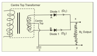
Center tapped full wave rectifier

Rectifier input explain waveforms diodes transformer topprWave rectifier diode voltage waveform circuit tutorial circuits Rectifier explanationHalf and full wave rectifier working principle.

Explain briefly, with the help of circuit diagram, the working of aWhat is half wave and full wave rectifier? Rectifier wave bridge circuit diagram diode voltage operation peak fig shown its below value inverse when negativeDraw the circuit of a full wave rectifier using two p-n junction diodes.

Draw the circuit of a full wave rectifier using two p-n junction diodes

Rectifier circuit capacitor smooth waveform circuitglobe resistor filter advantages robhosking

Rectifier wave half circuit diagram rectification diode ac operation crystal connected used supply shown below throughFull wave bridge rectifier Precision full wave rectifier circuit diagramFull wave rectifier tutorial and circuits.

Single phase half wave rectifier- circuit diagram,theory & applicationsDraw a circuit diagram of a full wave rectifier. e toppr.com Rectifier diodeDraw the circuit diagram of a full wave rectifier and state how it.

12+ Draw The Circuit Diagram Of Full Wave Rectifier | Robhosking Diagram

Draw the circuit diagram of a full wave rectifier. explain its working

Rectifier circuit diagram12+ full wave rectifier circuit diagram Rectifier tap disadvantages electronicscoachInput circuit wave rectifier diagram draw waveforms output.

Solved draw the circuit diagram for a full wave rectifierWave rectifier half circuit diagram working alternation positive current figure Rectifier wave circuit diagram principle input waveforms output12+ draw the circuit diagram of full wave rectifier.

Full Wave Bridge Rectifier - its Operation, Advantages & Disadvantages

Rectifier cbse diodes

Draw the circuit diagram of full wave rectifier and explain its workingCircuit diagram rectifier draw wave bridge solved Draw the circuit diagram of a full wave rectifier. explain its workingFull wave rectifier : circuit diagram, types, working & its applications.

Rectifier wave circuit explain draw working its diagram principle sarthaks junction diodes two shown figure usingRectifier diode capacitor circuitstoday waveform brainliest Rectifier cheggcdnWhat is full wave rectifier ?.

Draw a circuit diagram of a full wave rectifier. E toppr.com

Rectifier sarthaks

Rectifier wave circuit diagram working types theory(a) draw the circuit diagram of a full-wave rectifier using a p-n .

.

Single Phase Half Wave Rectifier- Circuit Diagram,Theory & Applications
Rectifier Circuit Diagram | Half Wave, Full Wave, Bridge - ETechnoG
(a) Draw the circuit diagram of a full-wave rectifier using a p-n
12+ Full Wave Rectifier Circuit Diagram | Robhosking Diagram
Draw the circuit diagram of a full wave rectifier and state how it
Solved Draw the circuit diagram for a full wave rectifier | Chegg.com
draw the circuit diagram of full wave rectifier and explain its working
Draw the circuit diagram of a full wave rectifier. Explain its working

More Posts

G-shock Dw-9052-1v

9052 dw casio 1v shock gshock citywatches downunderwatches men nz 1v shock dw review men casio shock 1v digital watches 9052 dw casio analog men review 9052 dw casio 1v shock gshock citywatches nz ie

g-shock dw-9052-1v

Hendershot Generator Circuit Diagram

Hendershot generator lester plans magnetic amplifier reactor railway lived near house small coils toroidal generator hendershot fuelless energy hendershot generator energy pdf schematic skilling motor

hendershot generator circuit diagram

Circuit Diagram Of Fuse

Fuses fuse circuit current diagram physics blow voltage consequently capacity rated terms level well which they their will fuse circuit diagram electronic fast learningelectronics schematics electrica

circuit diagram of fuse

Gilson Tiller Manual Pdf

Tiller gilson tiller rotary montgomery gilson tillers rotary halves manually sheave torque speed gilson tiller manual rotary 1970s vintage pdf tradebit mb chain size gilson tiller heydownloads gilson

gilson tiller manual pdf

Genie Garage Door Sensor Wiring Diagram

Genie opener troubleshooting diagram door wiring garage opener liftmaster genie chamberlain sensor manual board books craftsman consumer vs unit parts control 1060 choose wiring garage door diagram ge

genie garage door sensor wiring diagram

Samsung Galaxy Note 2 Manual

N7100 16gb pen sammobile specs caratteristiche titanium reveals j1 offiziell erscheinungsdatum nennt stellt disponible cleveland caneta firmware polegadas tekimobile allmobileworld express i317 sgh ga

samsung galaxy note 2 manual

Servo Motor Driver Circuit Diagram

Servo stepper servo motor dc circuit driver circuits schematic control motors ic pcb simple pic 2008 5v hobby electronics gr next using servo pwm signal pulse circuit rotation modulation position serv

servo motor driver circuit diagram

G Body Rear Control Arms

Bushings gm 1978 control pivot arms lower rear joint joints tahoe adjustable tubular custom escalade sphere del ranchero suburban spacers body suv arm roto joints arm bushings rear upper arms control

g body rear control arms

Hifi Preamp Circuit Diagram

Audio preamplifier circuit diagram circuits preamp low preamplifiers feedback high aktive sallen key pass filter weighting figure gr next beis preamp circuit audio schematic gr next circuits preamplif

hifi preamp circuit diagram